


Each dynamic impact coefficients of a bridge in bridge design aew always based on the overall dynamic responses of the bridges, which is generally the deflection or strain in the bridge, and such impact coefficients are determined based on the overall dynamic responses of the bridge are applied to the design of each component of the bridge. However, the structural system, the type of cross-section, the variety of construction materials, and the different members of the bridge mean that the impact effects of the vehicle loads from the impacts of the bridge is very different, as the current generalized specification of the bridge set by the overall impact coefficient are not enough, and need to be further tested. In contrast, the local impact effect happens to represent the impact effect on a single component of the bridge, which can make up for the deficiency of the norm set by the overall impact effect. In Wang33 used a similar method in this paper to study the impact coefficient of local components of long span suspension bridges, which proved the reliability of the research method. In this paper, the local impact effect of long span concrete-filled steel tube arch bridge components was carried out.
Effects on columns on arches at different vehiclels travel speeds
As one of the key components of load-bearing of long span deck type CFST arch bridges, the columns on the arch ribs not only have to transfer all the loads on the deck and main girders to the arch ribs, but also play the role of connecting the main girders with the arch ribs. As the most prone to damage, the vibration mechanism of the columns is also more complex, so it is necessary to study the local dynamic response of the columns on the arch, which is of great significance for the subsequent fatigue detection and damage assessment of the columns. Especially for the world’s longest deck type CFST arch bridge(Wujiang bridge), it has a total of 14 columns, with the tallest column as high as 78.975 m. In this section, the end columns near the junction piers, the middle columns at the L/4 section, and the top columns at the vault are selected as the key local research components of the bridge, and the speed is taken as the range from 0 to 36 m/s, and the local dynamic response of the bridge is investigated by a single vehicle loaded on the lane with a speed increment of 4 m/s. The top, middle, and top columns have a cross-section of 2500 × 1200 mm2, 2500 × 1500 mm2, 2500 × 2000 mm2, and 2500 × 1500 mm2, respectively.
Figure 14 shows the longitudinal and transverse displacement impact coefficients of the top columns, center columns, and end columns. impact coefficient of the transverse displacement of the top column fluctuates up and down in the velocity range from 0 to 24 m/s with little change, and then rises steeply after exceeding the critical velocity of 24 m/s, and finally has a leveling trend at 36 m/s. Change rule of the transverse displacement impact coefficient of the end column is similar to that of the top column, which fluctuates gently up and down in the velocity range from 0 to 12 m/s, rises steeply after exceeding the critical velocity of 12 m/s, and rises gently after the velocity of 20 m/s. The change rule of the lateral displacement impact coefficient of the central column is more complicated, fluctuating up and down throughout the velocity interval from 0 to 36 m/s, and reaching the maximum value at 4 m/s and 20 m/s. The maximum impact coefficient of the top column, middle column, and end column reached the maximum value at 36 m/s, 20 m/s, and 36 m/s, which are 0.138, 0.142, and 0.426, respectively, and the amplitude of the maximum impact coefficient of end column is 3.09 times that of top column and 3 times that of middle column.

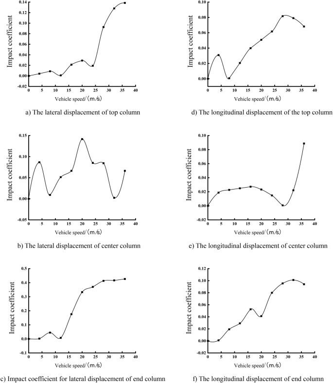
Curve of impact coefficients of transverse and longitudinal displacement of each column with different speeds.
The features of the relationship between the longitudinal displacement impact coefficients of each column with vehicle speed, the longitudinal displacement of the top column and the end column shows an overall increasing trend with the increase of vehicle speed, and the central column increases and then decreases in the speed domain from 0 to 28 m/s, and then increases steeply and reaches the peak value at 36 m/s. The peak longitudinal displacement impact coefficient of the end column is 0.101, which is 1.23 times that of the top column and 1.13 times that of the center column, respectively.
By analyzing the displacements of the columns in Fig. 15, it can be seen that the impact coefficients of the transverse and longitudinal displacements of the top and middle columns fluctuate in the range of 0 to 0.15 under the action of different vehicle speeds, while the impact coefficients of the transverse displacements of the end columns are as high as 0.426 under high-speed conditions. In terms of longitudinal displacement, the top column and the end column converge and rise gently, while the impact coefficient of the middle column is only gradually close to that of the top and end columns at high speeds after 28 m/s. The speed of impact coefficients of the transverse and longitudinal displacement of each column does not differ much, but the transverse and longitudinal displacement of end column is higher than that of top and center columns, especially end column in the transverse displacement of the impact mostly is effected by speeds. Compared with the other two columns, the larger and taller cross-section sizes of the end columns of the bridge are, transverse stiffness is smaller.

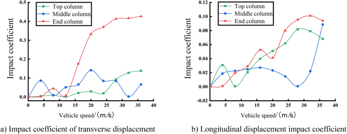
Curves of impact coefficients of transverse and longitudinal displacement of each column with different vehicle speeds.
From the Fig. 16, each column of the changing trend is generally the same, and fluctuations in the speed point are the same. However, the end column because of its paraxial cross-section size is larger, height is higher, and column stiffness and frequency are smaller, so in the impact of the vehicle load by the impact effect is greater, its stress impact coefficient amplitude for the top and the center of the 2.45 times, 3 times. The impact coefficient of the bridge as a whole is smaller than the impact coefficient of each column in the velocity range from 0 to 12 m/s, and larger than the impact coefficient of each column in the velocity range from 16 to 36 m/s, but still smaller than the stress impact coefficients of the end columns at the velocity points of 16 m/s, 24 m/s, and 36 m/s. Therefore, it is unreasonable to simply use a bridge’s overall impact coefficient to reflect the impact coefficient of vehicle loads on different local components, and the impact coefficients matching the components should be selected, according to the different local components of the bridge and the design requirements34.

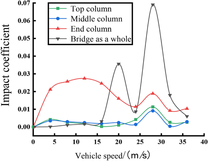
Relation curve of stress impact coefficient of each column with vehicle speed.
Effect of vehicle eccentric loading on arch ribs
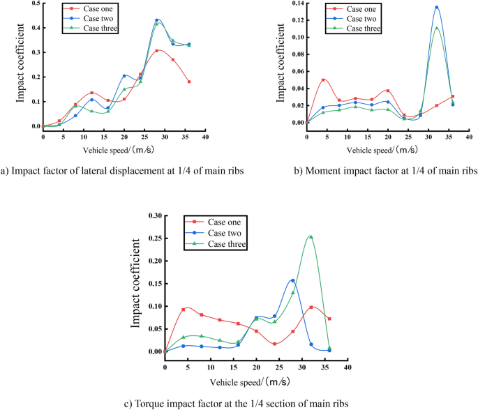
To further explore the influence of vehicle eccentric loading on the impact coefficient of the local components of the bridge, the top of the main arch and the L/4 section of the main arch are selected as the research object, and the working conditions one two three are formulated as a single vehicle loaded at the one, two or three lanes, taking the speeds of the vehicle as the range of 0 to 36 m/s, and the velocity is incremented by 4 m/s, to study the local response of the bridge under different working conditions. Among them, the transverse displacements of one, two, three lanes are 3.38 m, 0.37 m, and 3.85 m. Lane one is located on the inner side of the arch ribs and lanes two and three are located on the outer side of the arch ribs.
From the Fig. 17, each impact coefficient with the speed change in the relationship curves can be seen: the torque impact coefficient of the vault of the changes with the speed and the spacing is the largest, and the maximum difference between the impact coefficients of the various conditions is 0.146 at the speed of 32m/s. The lane eccentric loading on the vault’s torque impact coefficient is obvious, and the impact coefficient of the various impact coefficients is not simply positively correlated to the increasing distance and the increase of the eccentricity. In the transverse displacement of the vault, the trend of each condition is synchronized, and the two and three curves basically coincide, and the amplitude of the peak and troughness of condition one is always larger than that of the other two conditions. The three curves reach the peaks at the critical velocity points 12m/s and 24m/s, and reach the maximum value at 36m/s, and coincide basically. The greatest influence of eccentric distance of th vehicle on the impact factor of lateral displacement is the location of arch ribs, followed by the eccentric distance between the vehicle and arch ribs. Similarly, Case one which is on the inside of arch ribs, is subjected to the smallest impact coefficient of bending moment, followed by Case two, which is located closer to the outside of arch ribs. In the torque impact coefficient figure, the influence of condition one on the torque impact coefficient is greater than that of the other two conditions at low speeds, and the trend of the three condition curves is gradually approaching as the vehicle speed continues to increase. Therefore, the greatest influence of eccentric vehicle load on the local impact coefficient of arch ribs is the positional relationship between the lane and arch ribs, followed by the lateral distance from arch ribs.

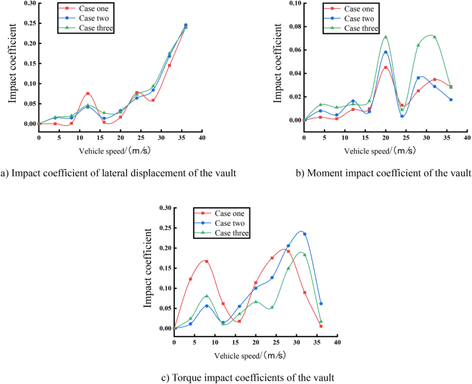
Curves of each impact coefficients of the vault under different vehicle speeds.
From the Fig. 18, it can be seen: the overall trend of the lateral displacement of the 1/4 section of main ribs is the same to that of the mid-span, but in more than 28m/s critical speed point began to decline as a whole, compared to the top of the main arch, so that the lateral displacement of the 1/4 section of main ribs reaches a maximum of the speed of the critical point in advance of the speed of the mid-span. In the change curves of the bending moment at 1/4 section of main ribs, the impact coefficient of bending moment of condition one is always larger than that of the other two conditions in the velocity domain from 0 to 28m/s. Beyond the critical velocity point of 28m/s, condition two or three begin to rise steeply, which is much larger than that of the impact coefficient of condition one, and the maximum difference of the impact coefficient is 0.115. In terms of torque, the curve trend of Case one, which is on the outside of the arch rib, is also very different from that of the other two cases, and the impact coefficient of Case one is always larger than that of Case two or three in the velocity domain from 0 to 16m/s, with a maximum difference of 0.081. The impact coefficient of Case one is smaller than that of Case two or three in the velocity domain from 16 to 36m/s, with a maximum difference of 0.236. Under different vehicle loading conditions, it is the torque that has the greatest effect on the local impact coefficients at the 1/4 section of main ribs, and for the same local member parameter, the gap between the vehicle loading position relative to the position of the arch ribs has the greatest effect on the impact effect, followed by the effect of the eccentric distance.

Curves of each impact coefficient at 1/4 of the main arch as a function of vehicle speed.
Influence of column stiffness on arch ribs
As the columns connected between the main girder and the arch ribs, the important role of the columns on the arch is self-evident. Based on the original model, the 0.6, 0.8, 1.0, 1.2, 1.4 times the column stiffness for different working conditions are taken, respectively, and the speeds of the vehicle for the range of 0 to 36 m/s are taken, and the velocity of the vehicle is increased by 4 m/s, to study the dynamic responses of the local bridge structure. The displacement and stress responses of the bridge under different speeds are calculated, and the local responses of the bridge under different column stiffnesses on the arch are showed as follows.
From the overall view of the features of lateral displacement, bending moment, and torque impact coefficient of the vault with vehicle speeds, the spacing of the curves in the feature of bending moment impact coefficients of the vault with vehicle speed is relatively smallest, so the changes of column stiffness have the smallest impact on the bending moment of the vault, compared with the lateral displacement and the torque. In Fig. 19a, except for individual velocities, the lateral displacement impact coefficient gradually decreases in the process of increasing the column stiffness from 0.6 times the original stiffness to 1.4 times the original stiffness in the whole range of velocities from 0 to 36m/s, which indicates that the lateral impact effect of the vehicle load at the vault is getting smaller and smaller with the increase of column stiffness. The reduction of the maximum dynamic effect at the main vault caused by the increase of column stiffness is larger than the reduction of the maximum static effect, thus showing an overall trend of becoming smaller and smaller. In Fig. 19b, the moment impact coefficients of the vaults under different column stiffness conditions reach the peak at the critical velocity of 20 m/s and then fluctuate discretely after exceeding 24 m/s. According to the comparison, like the mid-span deflection impact coefficient, the vault’s moment impact coefficient increases with the increase of column stiffness, but when it reaches a certain value of column stiffness, there will be a sudden change, resulting in a sudden decrease of the impact coefficient, and then continue to rise. In Fig. 19c, because of the many factors affecting the vault’s torque, the curves under the conditions of each column stiffness are relatively discrete and have no obvious regularity, but their undulating and fluctuating trends remain generally consistent. From the perspective of different column stiffness, the vault’s torque impact coefficient decreases with the increase of column stiffness, indicating that the vault’s torque under the influence of column stiffness, the maximum dynamic effect of the reduction is greater than the maximum static effect of the reduction, and thus subject to vibration effect is getting smaller and smaller. However, the impact coefficients of the torque at the vault are lower than the rest of the column stiffnesses throughout the velocity interval at 0.6 times the column stiffness, which may be the increment of the maximum static response of the torque at the vault is much larger than the increment of the maximum dynamic response at this condition, compared with the other stiffnesses, which reflects a lower impact coefficient overall.

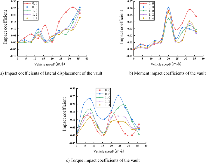
Curves of each impact coefficient of the main vault as a function of vehicle speed.
From the overall view, the maximum value of the impact coefficient of transverse displacement of the vault is located at 32 m/s under the condition of 0.6 times the original stiffness, and its value is 0.26. The maximum value of the impact coefficient of the bending moment of the vault is located at 20 m/s under the condition of 0.8 times the original stiffness, and its value is 0.06. The maximum value of the impact coefficient of the torque of the vault is located at 24 m/s under the condition of 0.8 times the original stiffness, and its value is 0.26. The maximum impact coefficient of transverse displacement and torque of the vault are both 4.3 times of the impact coefficient of bending moment. From a macroscopic point of view, the transverse impact effect of the vehicle load at the arch ribs of a top-loaded arch bridge is much larger than the longitudinal impact effect.
Compared with the above three figures, impact coefficient of the bending moment at 1/4 section of arch ribs is not sensitive to the change of the column stiffness relative to the transverse displacement and the torque at 1/4 of arch ribs. For Fig. 20a, it is not difficult to find that the curves under 0.6 times the original stiffness conditions are more discrete, unstable, and fluctuating compared with other curves. In the low-speed range from 0 to 8 m/s, there is not much difference between the stiffness curves, and in the medium-speed range from 8 to 24 m/s, the transverse displacement’s impact coefficient at 1/4 section of arch ribs decreases with the increase of column stiffness, which indicates that the impact effect on the transverse direction of 1/4 section of arch ribs is gradually reduced, but in the high-speed range from 24 to 36 m/s, the transverse displacement impact coefficient at 1/4 section of arch ribs changes with the stiffness of the column with no obvious pattern. In Fig. 20b, except for the 0.6 times original stiffness curves, the rest of the curves can keep fit, and the same undulation trend and the magnitude of the moment impact coefficient between the curves are very small. The reason may be 0.6 times the original column stiffness is too low, resulting in the column as a whole partial flexibility and instability, which in turn amplifies the impact effect caused by vehicle vibration when the vehicle load over the bridge. Therefore, too low stiffness should be avoided in the design of column parameters. From Fig. 20c, the same speed condition or the same stiffness condition of the torque impact coefficient with the change of the speed is not obvious, which indicates that there are many factors affecting the torque of 1/4 section of arch ribs, because the stiffness of the column and the driving speed is not enough to generalize the change of the impact effect of the vehicular loads.

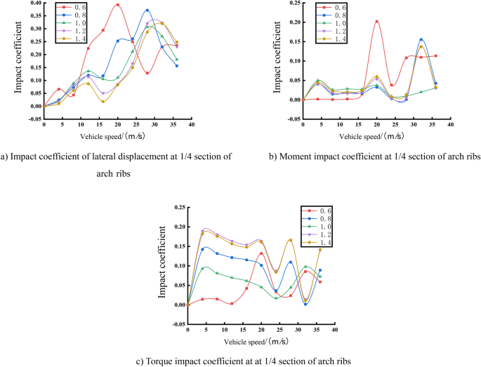
Curves of each impact coefficient at 1/4 section of arch ribs.
From the overall view, the maximum value of the lateral displacement impact coefficient at the 1/4 section of arch ribs is located at 20m/s under the condition of 0.6 times the original stiffness, and its value is 0.39. The maximum value of the bending moment’s impact coefficient at the 1/4 section of arch ribs is located at 20m/s under the condition of 0.6 times the original stiffness, and its value is 0.20. The maximum value of the torque’s impact coefficient at the 1/4 section of arch ribs is located at 4m/s under the condition of 1.2 times the original stiffness, and its value is 0.19. The torque’s impact coefficient at the 1/4 section of arch ribs is 1.95 times the original stiffness. At the macroscopic level, like the main arch, the transverse impact effect of the vehicle load at the 1/4 section of arch ribs of the deck type CFST arch bridge is much larger than its longitudinal impact effect, but the difference of its longitudinal and transverse impact effects is smaller than that of the longitudinal and transverse impact effects at arch ribs.
link